5. Soldering
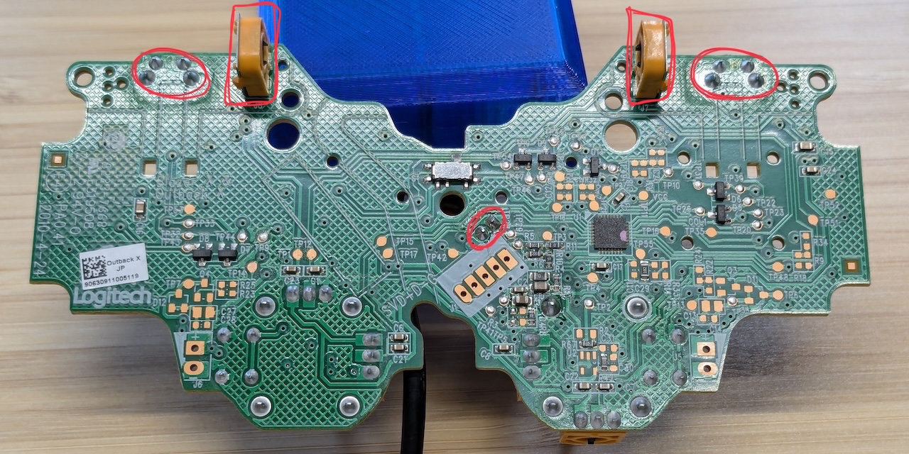
Remove the parts
The Logitech F310 is a bit thick as is, so start by removing the parts. Use a soldering iron to melt the solder and remove the parts, then use desoldering braid to clean up the remaining solder.
- The USB cable is detached to remove the ferrite core.
- The central rod (LED) is removed to reduce the height.
- The switches for LB and RB are removed to replace them with Cherry MX switches.
- The orange parts of LT and RT are removed to reduce the height.
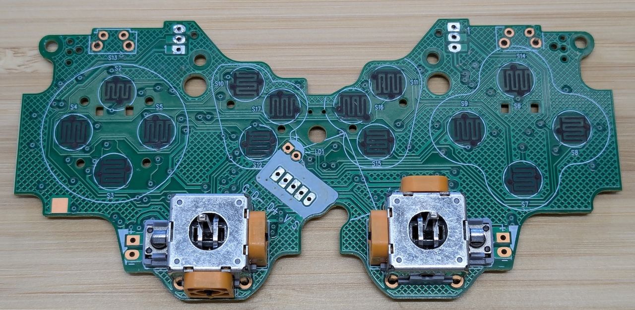
After removing the parts
| Before | ➡️ | After |
|---|---|---|
|
|
➡️ | 
|
|
|
➡️ | 
|
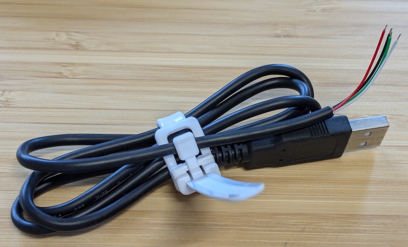
Snip the cables
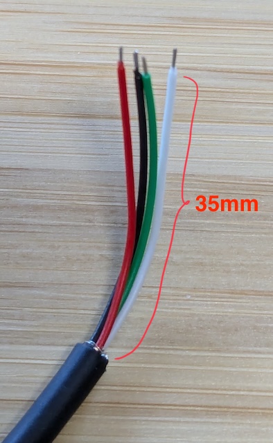
Cut the removed USB cable to a convenient length and strip the insulation.
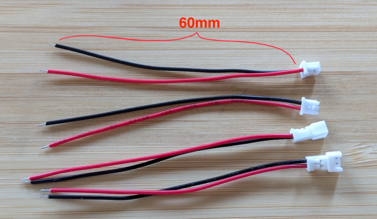
Cut the 2-pin Connector with Wires and strip the insulation.
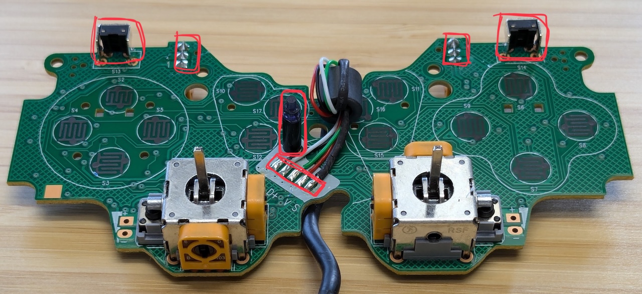
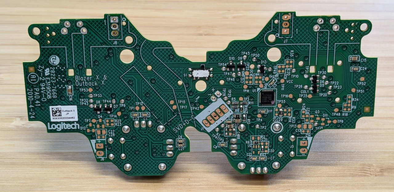
Solder the parts to the circuit board
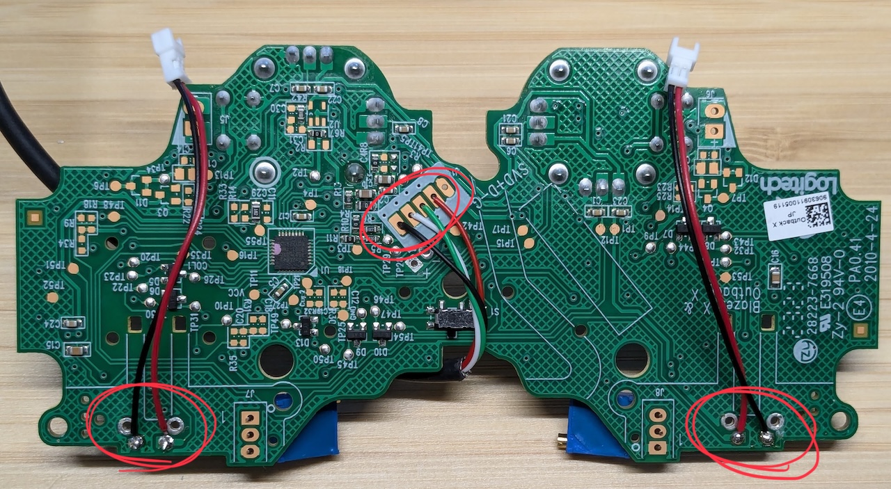
Solder the following parts onto the circuit board.
- USB Cable:
- Qty: 1
- The wire color is V D+ D- G-
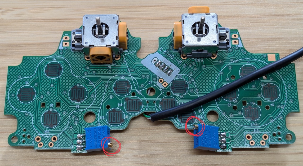
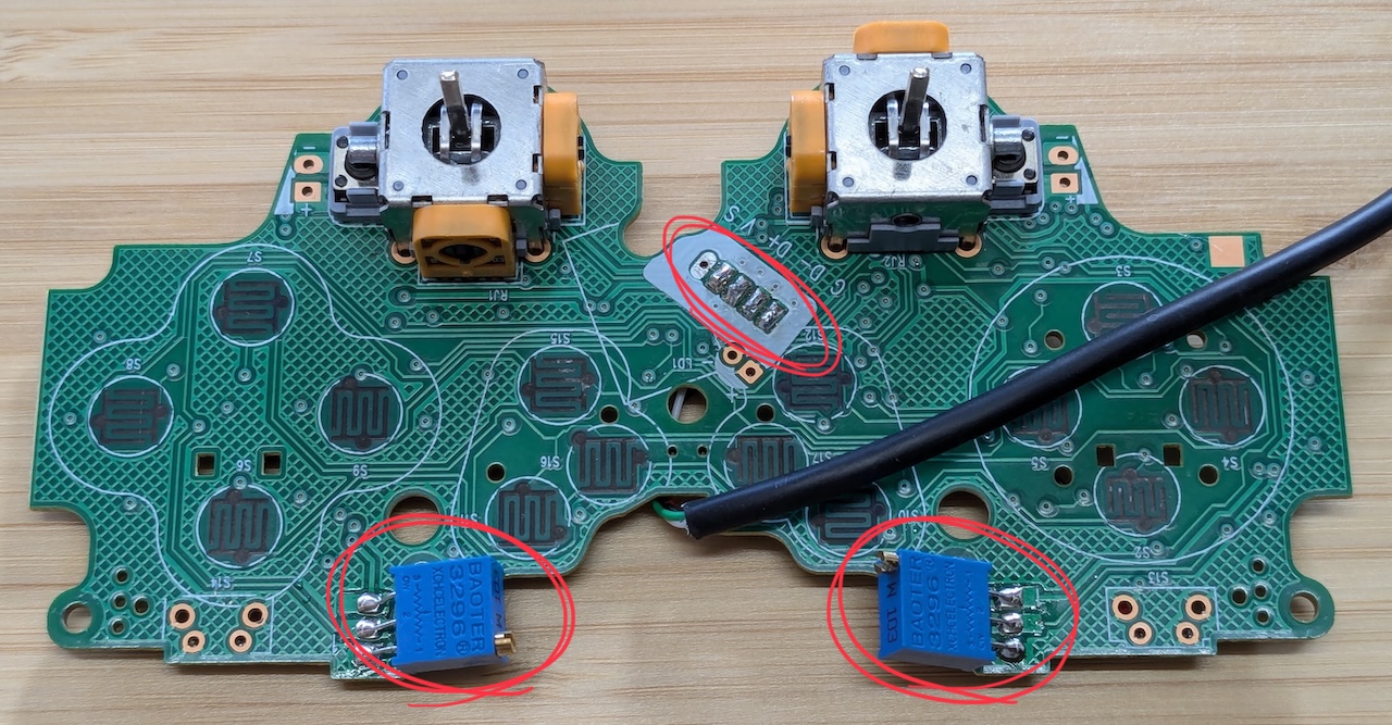
- 10k ohm variable resistors:
- Qty: 2
- The orientation of the resistor doesn’t matter.
- To prevent interference with the case, bend the leads inward as you attach them.
- 2-pin Connector with Wires (female):
- The color of the wire doesn’t matter.
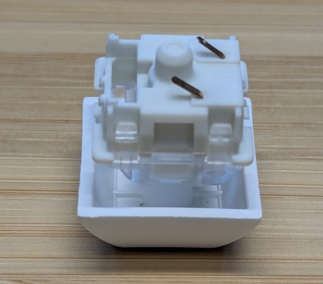
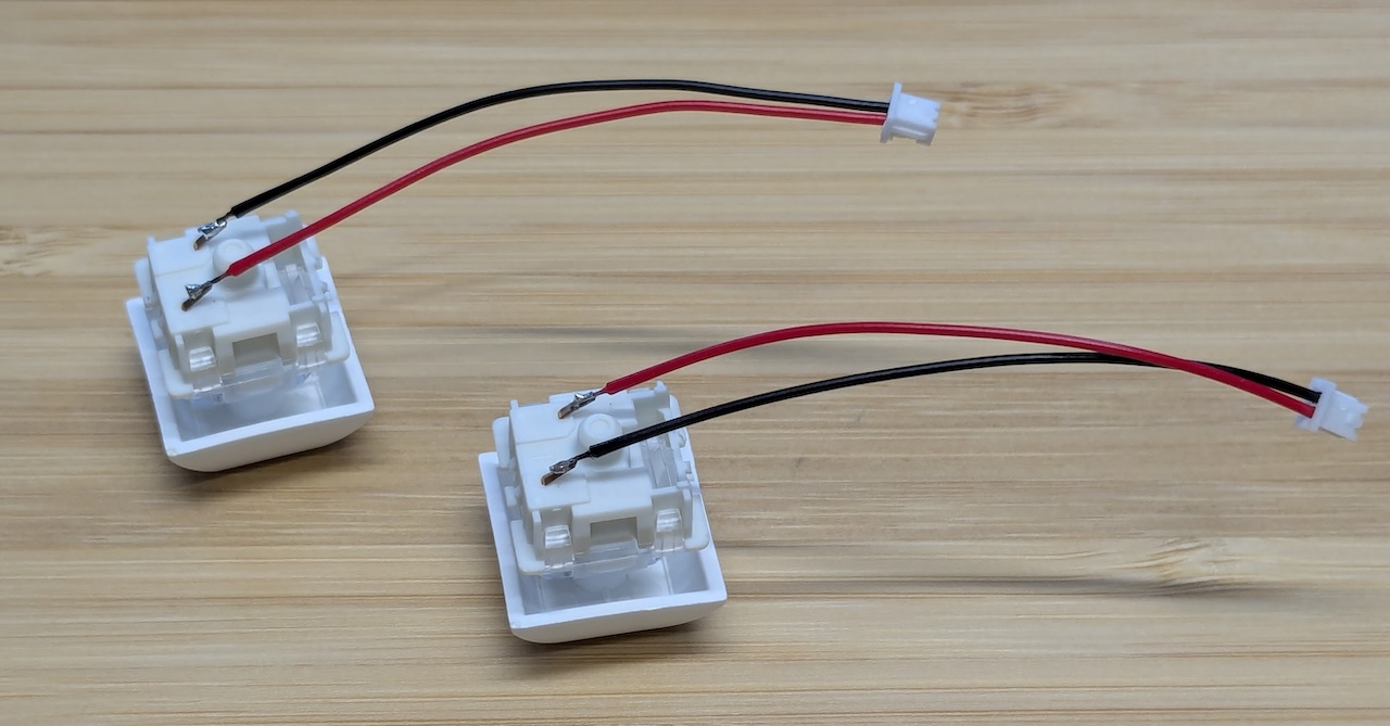
Solder the wires to Cherry MX Switches
Bend the switch pins, then solder the wires. The color of the wire doesn’t matter.
Verify the functionality
With the soldering complete, connect the Cherry MX switches to the circuit board, and then connect the board to macOS via USB. Ensure that the stick and buttons are working correctly.
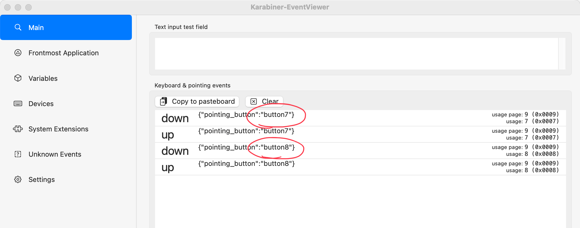
Tuning the variable resistor
The variable resistor is configured so that changing the resistance triggers button7 and button8.
You’ll need to tune the resistance to prevent these buttons from being activated.
Use EventViewer to adjust the variable resistor until both buttons are in the up state.